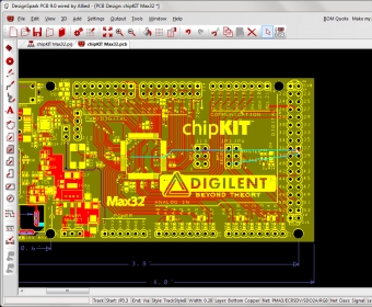
DesignSpark PCB (Printed Circuit Board) is a design tool based on a CAD system; its standalone interface means that the user doesn’t need to install it as an add-in for any other software. It is powerful and simple to use, free to use and loaded with the most complete parts libraries available.
Developing a PCB is easy. This software provides exactly the tools the designer needs for shaping the board, put the connection pads, the routes for the nets, add the copper shapes, and the copper-pour-areas, working in a schematic view to design the net, or in a PCB view to visualize the nets interaction, highlighting a specific net, viewing the components installed on each one displaying them with different colors.
As any other CAD system, this program also lets the user work in layers, assigning them different colors and properties. First, the software opens a PCB file by default with a board and its components. The user can close it and start from scratch, defining a folder and a path to store the new project, which is a good idea to keep all the documentation of each project ordered and easy to find later.
The user draws the board shape with the shape tool, drawing free hand or orthogonally (constrained to vertical or horizontal lines only), being able to type the exact coordinates for each new point, then the designer places the drag-and-drop components available in the library, making the connections, drawing the net and assigning the power connections.
Then the software enables the user to check error by using many different tools like a ruler to measure the board, a Design Rule Check tool that checks many features like the spacing for the tracks, pads, shapes, texts, drills and components, checking the manufacturing features like the minimum paste size or the Drill Breakouts, among others. The designer selects all the options to analyze and runs the analysis. Other tools are available to help the designer in the process. For instance, the Auto-place Components tool, which calculates the better position for each component according to where it was placed, the Auto- Route Nets tool, which checks all the nets for errors by feeding the maximum effort value, the number of passes the program should do and adding Vias, Side Pad exits as needed or restricting these values. The Auto- Rename components tool helps avoiding errors by assigning each component a different name.
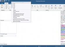
Once the design is completed, the designer can plot it into a PDF file or send it to a Gerber CNC router, a drilling base or other devices generating all the documentation needed for each department or person involved in the manufacturing process.
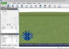
Another great feature is the ability to produce a 3D digital representation of the new design providing a better understanding of the designer’s intentions for other people.
Then the user can export the new design to an DXF, LPKF, or IDF document to share the project with other users that may not have this software or for the integration with the design of the casing in other programs with CAD capabilities.


Comments (3)
Any help should be highly appreciated.
Works best if both monitors are the same resolution, but it did work.