v9.0 [Dec 11, 2019]
DesignSpark PCB V9.0
New Features:
- Refresh Symbol in Component Editor. Now the application is aware if a symbol has been changed and saved and updates the symbol that is currently displayed in the previews windows.
- Resizable dialogs (Library Manager & Add Component) allow the left and right margins to be dragged to allow the full length of component names to be visible.
- Add Text – Now allows you to choose text style.
- Add Text – The text alignment allows the selection of Left, centred or right alignment
- Cross Probe single shot mode. Now you can escape from Cross Probe mode as soon as you select something, rather than staying in the mode where subsequent clicks would attempt to probe again.
- Dangling Connections Report in the Schematic design. Now you can easier discover in report places where you start a net from component pin and forget to finish or to assign to a net.
- Plotting dialog - buttons for Select/Deselect all layers. Additional buttons for easier and faster PCB layers display control.
- Library Wizards - Option for creating a “New Library” when saving a new library item hence a more convenient process.
- Goto bar – New box where you can type item name for faster navigating. Component list scrolls to the entered text and highlights the component once identified.
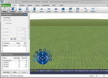
- Add to Net on Pour Area. Now have the choice to select nets that exist within the selected pour area, previously could only select from all nets in the design.
Fixes:
BOM Composer:
- The sort order in the CSV file generated by BOM Composer was not the same as that shown in the on-screen display or the generated HTML/text report.
- Some standard reports in BOM Composer did not attempt to populate the Part Number column from all possible component Values in the design.
Design Tool Tips"
- Depending on the Zoom level, the on-screen design tool tip could show information for the wrong item.
Display"
- In several places in the application the display of user interface elements (including some dialogs, and list boxes containing check boxes and/or icons) was incorrect or unreadable on high-resolution displays.
Drawing"
- At some zoom levels and grid steps, drawing of screen grid dots could be very slow causing application to become unresponsive.
Gerber Output"
- When generating Gerber data using the “X2” format, the aperture function ‘SMDPad’ in the file header was missing a mandatory second field (‘CuDef’ or ‘SMDef’).
Project Files"
- When saving a copy of a Project, an error message was being displayed that incorrectly indicated that the copied Project would not work properly.
Rename Component"
- Renaming selected components in a PCB design could result in some of those components being given names that already exist on non-selected components.
- In some situations, components on some Schematic sheets in a Project were being overlooked.
- The setting of the ‘By Stem’ checkbox when using Auto Rename Components in a Schematic was not being remembered for next time the dialog was used.
Reports"
- The supplied ‘RSBOM’ report did not attempt to populate some columns (including manufacturer and manufacturer part number) from all possible component Values in the design.
Setup"
- The installer was not applying the correct application icon to be displayed in the Windows ‘Apps and Features’ control panel.
File selection"
- Improvements have been made to remove occurrence of the widow becoming inactive.
Problem Fixes in Version 9.0.2:
- Windows OLE registration issue fixed to allow DSPCB to correctly interface with Library Loader.
- Technology path not set to correct path on installation or retaining path when corrected.
Problem Fixes in Version 9.0.3 :
Add Component:
- Stretching the Add Component dialog was not increasing the amount of space for the list of component Values.
Add Track:
- The default action when clicking to insert a corner over an existing track segment on another layer was to ask to insert a via and join to that track, instead of offering this as the default only if both tracks were on the same net.
Colours:
- Poured Copper was being drawn using a colour that was not available to be changed on the Colours dialog.
Component Edit:
- After saving edits on a symbol whilst having a component open for edit, sometimes the symbol preview would not update to show the newly-saved symbol until you closed and re-opened the component.
Component Values:
- It was not possible to Import a CSV file that had just been Exported from the Components page of the Libraries dialog.
Delete:
- When deleting a Pour area, the choices offered on the popup question about removing the associated copper did not match the actions that the application then took in response to your choice.
Design Technology:
- Grids were not visible on Design Technology and various other dialogs on some high-resolution displays.
v8.0 [Dec 13, 2016]
- Fully featured Measure Tool.
- A ‘spreadsheet’ style Component Values dialog.
- New Unroute Preference - “Delete Track Does Unroute”.
- Improved resolution Gerber output files for arcs in pads rounded corners using shapes such as Rounded Rectangle.
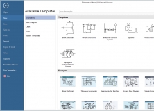
- Improved “File New” dialog window.
- New BOM Quote functionality realization.
v7.2 [Jun 16, 2016]
New Features
Fully featured Measure Tool.
A ‘spreadsheet’ style Component Values dialog.
New Unroute Preference - “Delete Track Does Unroute”.
Improved resolution Gerber output files for arcs in pads rounded corners using shapes such as Rounded Rectangle.
Improved “File New” dialog window.
New BOM Quote functionality realisation.
For full list of new features please visit DSPCB Support Centre
Fixes
The ‘Top Coloured’ setting for ‘Can’ packages causing the top of the can to always be drawn in the same colour as the body repared.
Repaired preference setting ‘Add Component Keeps Library Style Sizes’ which was not having any effect on how styles of newly-added components were matched to styles already in the design.
Holding the Ctrl key when adding squares or triangle now alter the shape to be centred around the cursor position.
Auto Rename of components across a multi-sheet Schematic or multi board design which caused fail to rename some components.
Design Rule Check for Component-to-Component checking caused, in some circumstances, the generating of a spurious error indicating that two components were overlapping when in fact they were not.
Eagle Import improved for duplicate named line, track and text styles could be created when importing Eagle files. Component and symbol names longer than the allowed 30 character are now allowed.
Gerber output problems when creating a solder paste plot for pads using the Annulus pad shape or when precision for the corners of Rounded Rectangle pads was too low – are now working correctly.
IDF output for coordinates and insufficient angular resolution problems are patched.
Libraries are improved for various problems including copying an item, some AMP footprints and the report button of the Library Manager dialog to search for components.
PDF output improvements when generating a set of plots to separate PDF files as well as previous problems with TrueType fonts.
For full list of fixes please visit DSPCB Support Centre
v7.1 [Aug 13, 2015]
Back Annotation.
Would not handle name changes where only the ‘case’ of a name was altered.
Change Component.
Replacing a two-gate component with one having only a single gate could cause the application to hang.
Design Rule Check.
One specific PCB design had several spurious pad-to-copper errors reported.
DXF import.
some circles were being imported in the wrong location.
Gerber output.
Default minimum coordinate resolution increased to 5 places to reduce likelihood of rounding errors.
Measure.
The wrong distance was being reported when measuring between two silkscreen shapes.
Move.
Moving track segments could move vias at the end of those segments even though the vias were marked as fixed.
v7.0 [Nov 27, 2014]
This version solves the following issues:
1. Add Track
- When using Orthogonal mode, sometimes some track segments were being left in ‘dynamic’ mode, which meant they became invisible when the picture was redrawn.
2. Authorisation
- Error messages displayed to indicate a problem with software authorisation sometimes contained unreadable characters.
3. Cross-Probe
- Some nets in a Project could not be cross-probed if schematic sheets had been removed from the Project then re-added.
- Attempting to cross-probe a net from Schematic to PCB in a single-sheet Project was not finding the net in PCB.
4.Design Technology
- Sorting items in tables into order did not take account of values to the right of the decimal point.
- It was possible to set Isolation Gap to a negative value, causing issues with Pour Copper.
5.Drawing
- Redrawing the picture was slowly consuming GDI Objects, eventually causing the application to quit, usually after several hours of usage within one application session.
- Circles for drilled-out free pads were sometimes being drawn away from the pad to which they belonged.
6. DXF
- Some DXF files use codes 41 and 42 as an alternative to code 43 to define a POLYLINE, which was not being detected in the DXF Import module.
- DesignSpark Mechanical compatibility issue resolved.
7. Forward Design Changes
- Running Forward Design Changes after renaming a sheet in a Project would sometimes unroute more tracks in the PCB than strictly necessary.
8. Library Manager
- Creating a new library would frequently offer to save it in a folder that was not in the library folders list.
9. ModelSource
- Could use the wrong Technology file for the preview of components in the ModelSource bar.
10. ODB++
- Some pads were being incorrectly isolated from their plane when the thermal connection width was over a certain size.
11. Pour Copper
- One specific design containing pads with overlapping copper shapes used to create ‘custom’ pads would not isolate those pads from the plane during Pour.
v6.1 [Sep 3, 2014]
Due to space constraints, we deeply regret that we have not been able to provide the compelete change-log for this version of DSPCB below. We have included only 10 (out of 26) change-long entries below. The interested reader may visit http://www.rs-online.com/designspark/electronics/eng/knowledge-item/designspark-pcb-change-log to view the full change-log.
1. 3D View
Prism shapes in user-defined packages were not being inverted for a component that had been placed on the back of the board.
When package type is set to DILSwitch, if it happened to match with a PCB symbol containing only a single pin, the application would quit while attempting to generate the 3D impression.
When creating a new 3D package, sometimes the details would not be saved the first time round, requiring the details to be entered a second time before the new package would be saved to the library.
Each successive redraw would increase memory usage.
2. Change Style
Changing the track style of a zero-length track between a via and a pad at the same location could cause the application to quit as the track is tidied out after making the style change.
3. Design Rule Check
Component-to-Component checking was being done using the ‘edges’ of the component bounds, rather than treating the bounds as a ‘solid’ box, thus leading to fewer errors being reported than should have been the case.
4. DXF Import
Certain commands were not being interpreted correctly in DXF files in recent formats, potentially leading to nothing appearing in the design after import.
5. DXF Output
Long layer names could cause the DXF file to be unreadable in other software such as AutoCAD and TrueView, despite the published length limit of layer names being 255 characters.
Text items could be misplaced from their proper locations.
6. Gerber Import
The holes defined by drill files were not always being matched to the corresponding pads during Intelligent Gerber Import, resulting in pads without holes.
If the folder where the import process tried to write its report file was not writeable, the application would quit.
7. Goto
The Goto bar would sometimes retain information (such as Component names) from a design that had been closed or reloaded, which would cause the application to quit if you clicked on any of those items.
8. Library Manager
The presence of a comma in the name of a 3D package could cause the application to quit as it encountered that name when reading the 3D library.
9. Forward Design Changes
In designs containing some types of PCB-only component, running Forward Design Changes or Integrity Check could cause the application to quit as it attempted to generate the report.
10. Startup
On a tiny number of machines, usually running Windows 7, the application would ‘block’ on startup after a Windows API function call failed to return. The application process would be visible in Task Manager but nothing would be displayed on the screen.
v6.0 [Jan 21, 2014]
21/01/2014 - Version 6.0
Overview video for the new features in Version 6:
1. Simplified DesignSpark Mechanical IDF export - for easier exporting to DS Mechanical 3D design tool
2. Cross-Probe - for faster hardware debugging and navigation around designs
3. Custom Shortcuts - add user-defined keyboard shortcuts for personalisation of UI
4. Start Page - lists useful highlights, reference designs, getting started links and the handy list of recent projects/files
v5.1 [Nov 13, 2013]
1. ModelSource Component Reference error - this fixes incorrect RefDes or Component ID issue
2. ModelSource Fails to read XML with “>” character in a value - this fixes display of some of the library families previously resulting in a 'communication error'
3. Component Edit: Name Pins by Row/Col can sometimes fail to apply new names
4. Librariy Manager: a malformed unnamed library item could cause the application to quit
5. PDF Outputs: mirrored text on PDF plots was slightly undersized
6. Layout: Add shape using "=" to type in start & corners does not work if orthogonal segment mode
7. Opening files: Reloading a design can sometimes cause the application to quit if Interaction Bar has been closed
v4.0 [Oct 18, 2012]
PCB Quote service – instant prototype board manufacturing quotes, directly from DesignSpark PCB application.
BOM Quote service – instant access to on-line component quoting, directly from DesignSpark PCB application.
A library interface that links to our ModelSource database, with instant access to over 80,000 footprints and symbols.
v3.0 [Nov 8, 2011]
Version 2 enhancementes also include:
- Bitmap Export
- New Library Functions
- Extra project features
- Enhanced Excellion Drill plots
- Additional Grip and placement options
-